


Munich, Germany, August 12, 2024: Kitekraft, the pioneering developer of airborne wind energy systems (a.k.a. flying wind turbines), announces today that it has completed several flights with full sensor redundancy and other reliability enhancements. With these new developments, a Kitekraft system is now so robust, that any sensor at the kite or at the ground station can be lost, but the system detects that failure, remains in a safe state, and lands normally in hovering to the ground station for inspection. This capability marks another milestone for Kitekraft and its focus on safety and high reliability. Also, new updates on our Anti-Collision Lights, the better and better alignment between reality and simulation data as well as a new flight test video.
If a Sensor Fails, it is Noticed and Rectified Within 25 Milliseconds
With the amount of sensors our systems operates with, it would be too much to go into every detail of our redundancy approach. Instead, we dive a deeper on a specific example: The tether is attached to a two-axis gimbal assembly at the ground station, which allows for defined load transfer, and avoids any wear and tear of the tether. The two axes are elevation and azimuth, whose angles are each measured redundantly by two magnetic contactless potentiometers mounted on each rotation axis. This means, if e.g. the two azimuth potentiometers do not show the same angle, it is immediately detected that something is wrong and flagged as a fault. This check is done within each control loop executed every 25 milliseconds. Such a fault can be caused both, by some mechanical failure or some electrical failure. Primarily a fault is mitigated by high quality parts and good quality control. But because the probability for a fault occurring is inevitably higher than 0% and only a no-single-point-of-failure-design, which is Kitekraft’s design goal, can adequately handle and react to a fault, it actually is not too relevant to know what the cause is. If the angle of the faulty potentiometer is unrealistically far off, it is immediately detected as the faulty one by the software control logic and the other healthy potentiometer is used instead. If the angle is just a bit off, so that it is unclear which potentiometer is the faulty one, things get more interesting. In this particular case, the software is programmed to decide that no potentiometer can be trusted and other values like the GPS is used to identify all necessary values (e.g. position of the kite) needed by the control algorithms. When a fault occurs, the kite is then landed normally at the ground station such that the fault can be inspected and rectified.
Kitekraft’s engineers permanently test the proper behavior of the fault detection, handling and control algorithms thoroughly with Monte Carlo simulations. Additionally, machine hall hovering tests are performed, in which connectors are unplugged or faults are provoked and emulated otherwise via software, to validate the intended behavior in reality. All those tests have been successful.
New Anti-Collision Lights (ACLs) for Safety in Low-Visibility and Night Conditions
Kitekraft has implemented the in-house developed Anti-Collision Lights (ACLs), which are mounted redundantly on both the kite and the ground station. There are 4 ACLs on the kite and 4 ACLs on the ground station, both to enable visibility from every direction and to provide tolerance against a fault if one light fails. All ACLs blink synchronized in a double-flash pattern, enabled by the communication cables inside the tether and controlled by the kite’s onboard computer. This allows a pilot of another aircraft approaching to visually identify the kite and the ground station (with the tether in-between) as one system. The ACLs are green according to European Union Aviation Safety Agency (EASA) rules for Unmanned Aerial Vehicles (UAS).
Below is an uncut video of one of Kitekraft’s previous test flights with full sensor redundancy and ACLs in action. The purpose of this flight was to validate the functioning of the full sensor redundancy and validate improvements of the control algorithms.
Good Match between Flight Test Telemetry Data and Simulation
A large amount of Kitekraft’s development efforts goes into making sure that our simulation models are representing reality as good as possible. The simulation is part of the in-house developed C++ Systems Engineering Framework, which also incorporates controllers, optimizations, and much more. With such a “kite simulator”, Kitekraft engineers can test improvements to hardware and software, like changes in the wing configuration or flight algorithms, very quickly and at very low cost, and therefore maximize the system’s reliability and efficiency quickly. In simulations, if something goes wrong, the algorithm can simply be corrected, and the simulation can be restarted.
This is used heavily to improve Kitekraft’s hardware and software. Between test flights, there may be dozens to hundreds of improvements, to make the system and kite’s flight more reliable against component failures, robust against wind gusts or directional changes, and more efficient. This is also a crucial tool for the work on the next generation 100kW product version system.
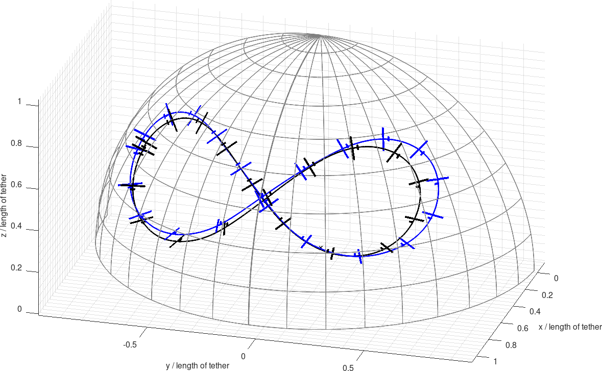
Below is the plot of the position and orientation of the kite recorded during one of the recent flight tests (telemetry data drawn in black), which is compared to the simulation computed with same environmental data (simulation data drawn in blue). The close to perfect match of both graphs indicate a very good match of simulation and reality.
Full 1h+ Flight Uncut Video
Kitekraft is performing more and more flights, with ever increasing robustness and efficiency. The team is continuously increasing the flight time and flight envelope. Below is an uncut video of the onboard-mounted camera of one of Kitekraft’s recent test flights which spans over 1h of figure-8 flight with 159 flown figures-8s and 90km of traveled distance.


